Tutorial: Traffic Light Model
In this tutorial you will create a simulation model in Studio Technix of traffic lights at an intersection. The traffic lights will follow a predetermined sequence. In the next tutorial, the traffic lights will be actively controlled by an embedded software program.
Creating a new project
Open the Studio Technix application. The welcome screen appears.
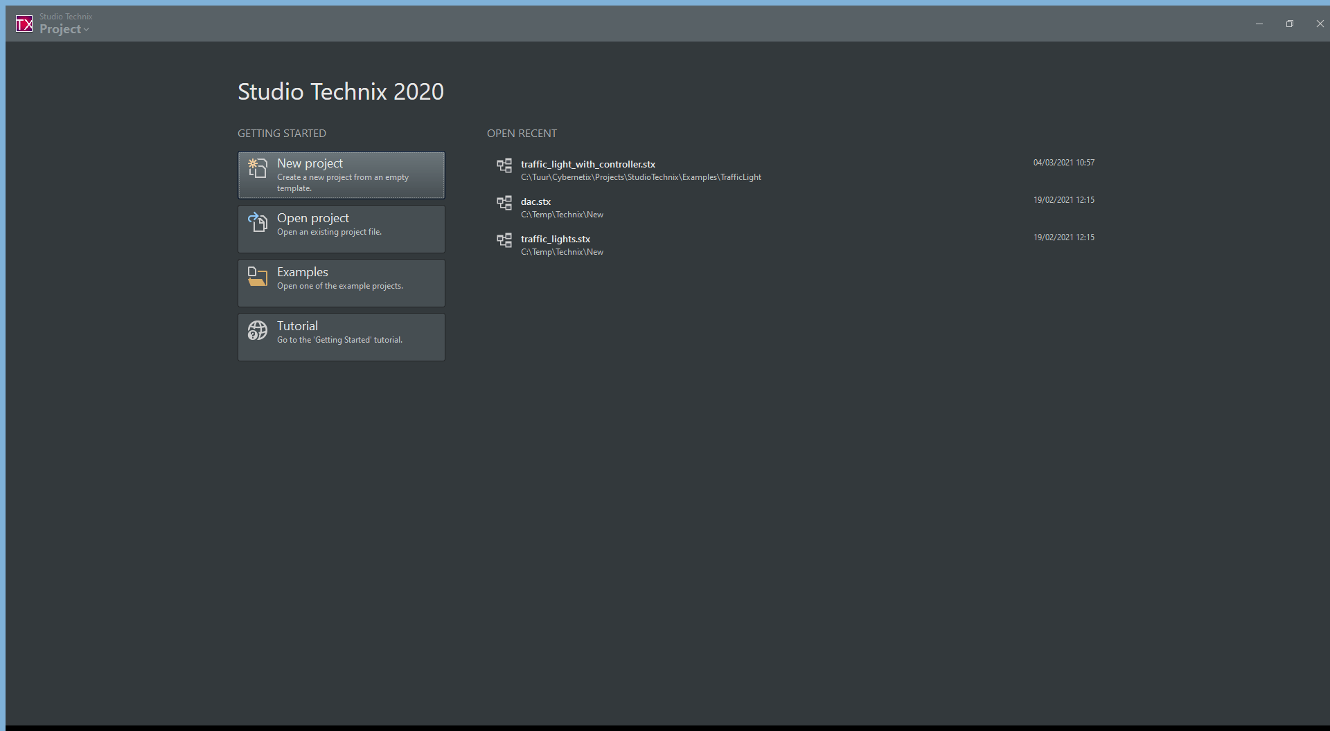
Click on New Project to create a new, empty project.
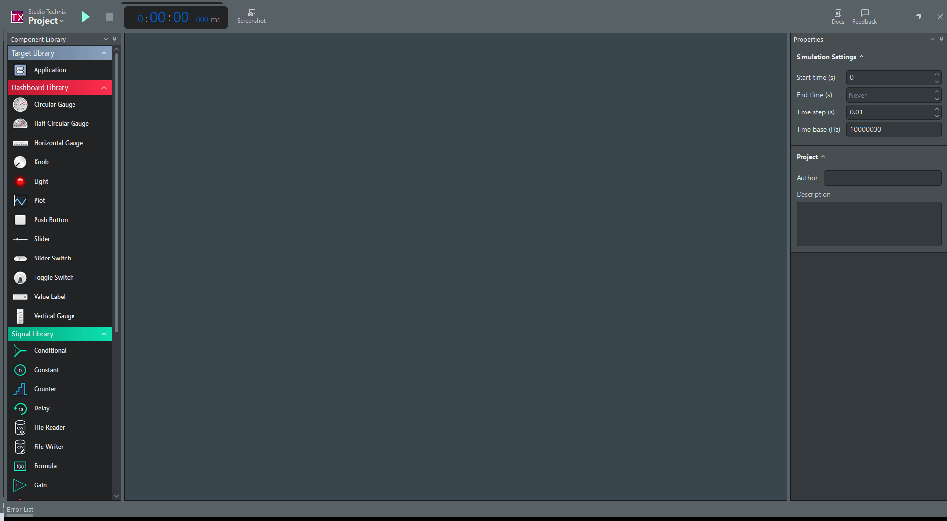
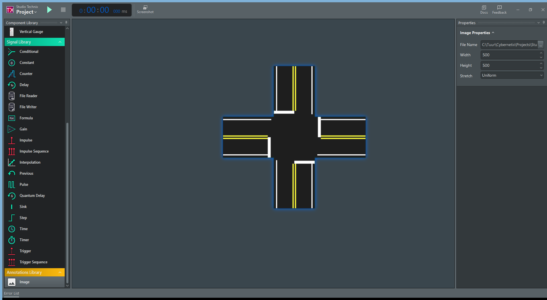
The main window appears.
Modeling the intersection
Adding a background image
To better visualize the intersection, first, a background is added.
Download the road background or right click on the following image to save it.

Next, in the Component Library panel, scroll down to the Annotations Library and locate the Image component (
 ).
).Drag the Image component from within Component Library to any location in the empty Diagram workspace.
An icon of an image appears on the Diagram, representing the newly added Image component instance.
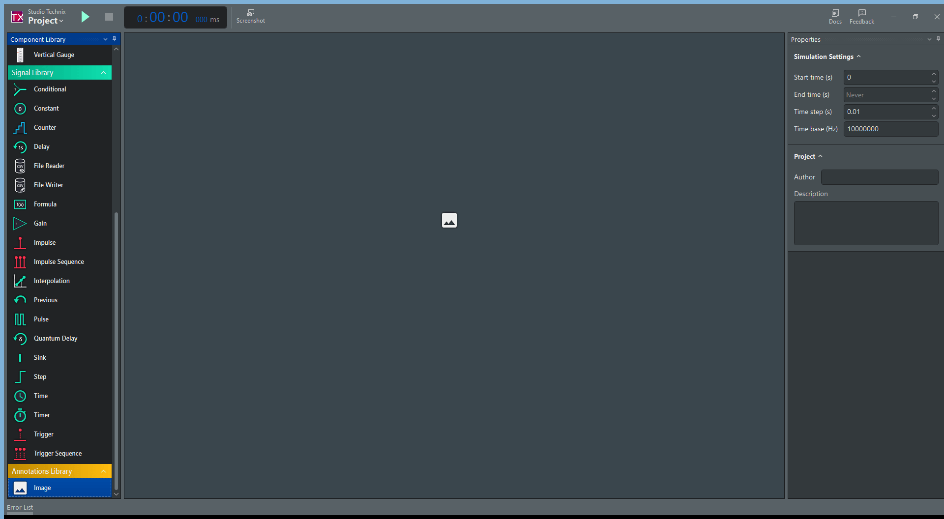
Click on the image icon to select it.
The Properties panel changes to show the properties of the Image component instance.
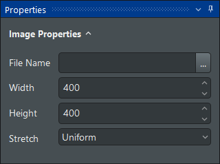
In File Name edit box, click on the button '...' to select the road.png file.
The image icon in the diagram changes into the road background.
Set both the Width and Height parameter to
500.
Adding Light components for the side road
In this section the lights of the side road are added.
- In the Dashboard Library, locate the Light component (
 ).
). - Drag the Light component onto the Diagram and place it to the right of the bottom road section. This component represents the Red traffic light of the side road.
- Drag a second Light component onto the Diagram and place it below the previous Light component.
- Click on the second Light component to select it, and set its Color parameter to
##FFFF6E00. This component represents the Orange traffic light. - Drag a third Light component onto the Diagram and place it below the previous Light component.
- Click on the third Light component to select it, and set its Color parameter to
##FF33FF00. This component represents the Green traffic light.
The model now looks as follows.
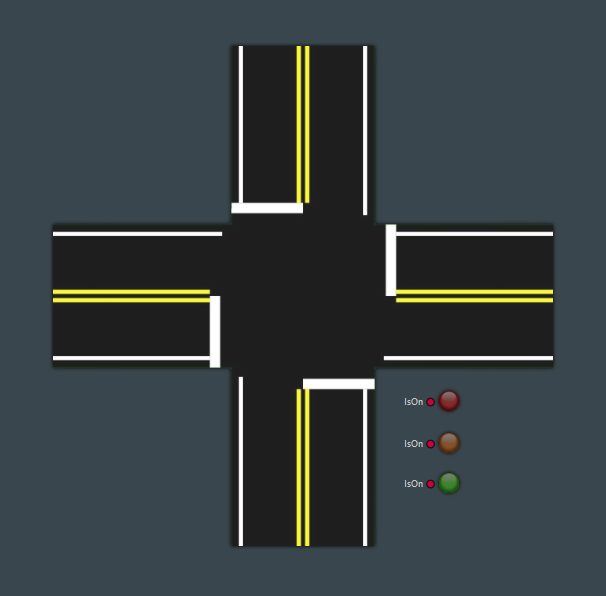
Note that each Light component has an input port, called IsOn. Later on in this tutorial, these ports will be connected to other components such that the state of the light can be changed during the simulation.
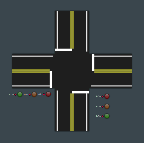
Adding Light components for the main road
The process is the same as that of the previous section.
- In the Dashboard Library, locate the Light component ().
- Drag the Light component onto the Diagram and place it underneath the left road section. This component represents the Red traffic light of the main road.
- Drag a second Light component onto the Diagram and place it to the left of the previous Light component.
- Click on the second Light component to select it, and set its Color parameter to
##FFFF6E00. This component represents the Orange traffic light of the main road. - Drag a third Light component onto the Diagram and place it to the left of the previous Light component.
- Click on the third Light component to select it, and set its Color parameter to
##FF33FF00. This component represents the Green traffic light of the main road.
The model now looks as follows.
Generating a traffic light pattern
The traffic light pattern follows a repeating sequence with a total duration of 16 seconds:
- All lights are Red for 1 second.
- The main road light turns Green for 5 seconds.
- The main road light turns Orange for 2 second.
- All lights are Red for 1 second.
- The side road light turns Green for 5 seconds.
- The side road light turns Orange for 2 second.
- Back to step 1.
Using a Counter to generate a repeating sequence
A Counter component is used to generate a sequence of 16 steps.
In the Signal Library, locate the Counter component (
 ).
).Drag the Counter component anywhere on the Diagram to the left of the Intersection image.
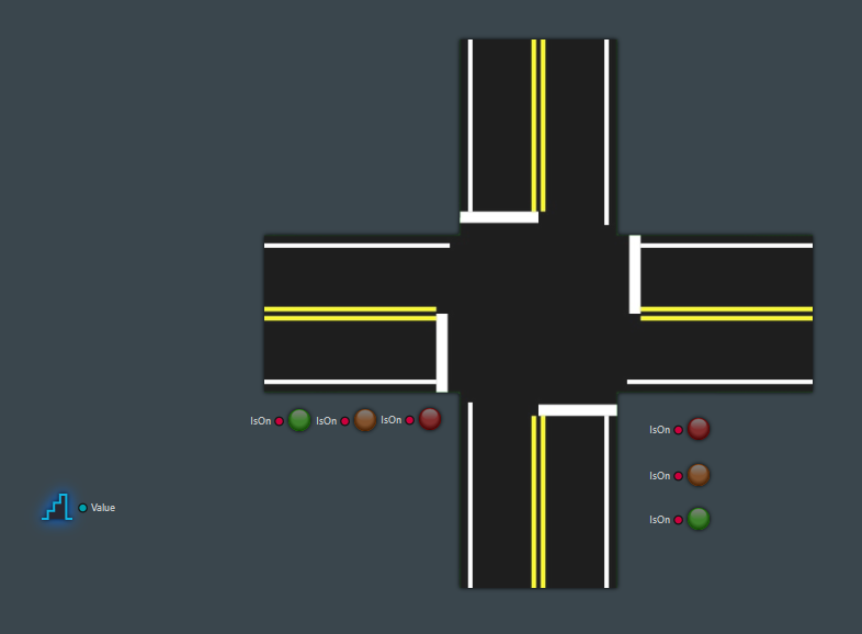
Click on the Counter component to select it.
Set the DataType parameter to
Int64.Set the UpperLimit parameter to
15.Leave the StartTime, SamplePeriod and Offset parameter to their default values of respectively
0,1and0.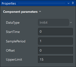
With these settings, the counter component generates a step-wise increasing signal at its output port Value, counting up by 1 every 1 second, from 0 to (and including) 15. After that the counter is reset to 0.
Using a Formula component to switch on a Light within a specific interval
To turn on a light in a specific time interval, the formula component is used.
- In the Signal Library, locate the Formula component (
 ).
). - Drag the Formula component and place it on the diagram between the Counter the intersection image.
By default, the Formula component has one input 'x1' and one output 'y1' of type Float64.
The Formula component will be configured to have one input and three output ports. During the simulation, the input will receive the signal from the Counter component, and the three outputs will emit the state of the Red, Orange, and Green traffic lights.
Click on the Formula component to select it.
In the Inputs section of the Properties panel:
Rename the input port 'x1' to 'Time'.
Set the data type of 'Time' to Int64.
In the Outputs section of the Properties panel:
Click two times on Add Output to generate two additional output ports 'y2' and 'y3'.
Rename the output port 'y1' to 'Red'.
Set the data type of 'Red' to Bool.
Rename the output port 'y2' to 'Orange'.
Set the data type of 'Orange' to Bool.
Rename the output port 'y3' to 'Green'.
Set the data type of 'Green' to Bool.
A formula specifies during which time a specific light is turned on (true) an during which time the light is turned off (false).
- In the Outputs section of the Properties panel:
Set the formula (next to the '=' symbol) of the 'Red' output to
(0 <= Time && Time < 1) || (8 <= Time && Time < 16)This will turn on the Red light from second 0 to 1, as well as from second 8 to 15.
Set the formula of the 'Orange' output to
6 <= Time && Time < 8This will turn on the Orange light from second 6 to 8.
Set the formula of the 'Green' output to
1 <= Time && Time < 6This will turn on the Green light from second 6 to 8.
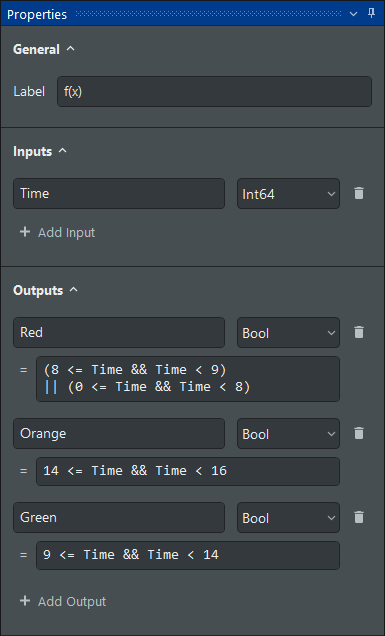
The property panel of the Formula component should now look as follows:

Repeat the process above to add a second Formula component, with the same properties as the one above, except for the formulas:
Formula of the 'Red' output:
(8 <= Time && Time < 9) || (0 <= Time && Time < 8)Formula of the 'Orange' output:
14 <= Time && Time < 16Formula of the 'Green' output:
9 <= Time && Time < 14
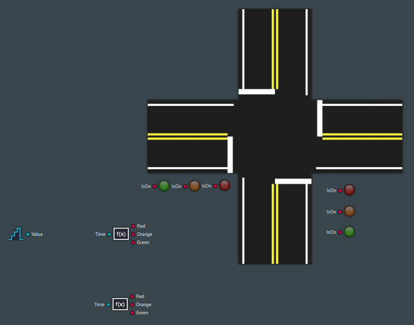
The resulting model looks as follows:
Connecting the components
Components represent different parts of the system. To complete the model, connections between the input and output ports of the components need to be made that specify the flow of information between the components.
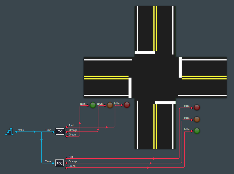
Complete the diagram as follows.
- Connect the Value port of the Counter component to the Time port of both Formula components.
- Connect the Red, Orange, and Green ports of the first Formula component to the IsOn port of respectively the red, orange, and green Light components of the main road.
- Connect the Red, Orange, and Green ports of the second Formula component to the IsOn port of respectively the red, orange, and green Light components of the side road.
Where necessary, drag the corners of the connections to reshape the link.
This completes the model.
Saving the project
To save the project:
- In the Menu bar, click on Project (
 ) to open the Project backstage window.
 - Click on Save and name the project as
TrafficLightModel.
Running the simulation
With no components selected the Properties panel shows the Simulation Settings.
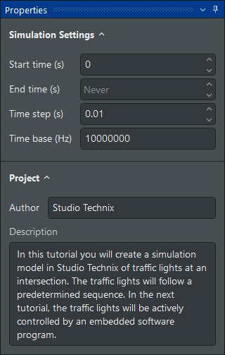
The settings can be left at their default values. No End Time is specified, so the simulation will run forever.
To start the simulation:
- In the Menu bar, click on the Play button (
 ).
).
The Simulation starts to run, and you should see the following animation in real-time.
This completes the tutorial.
In the next tutorial the predefined sequence will be replaced by an active controller written in C-code that determines the state of the lights based on a sensor that detects vehicles.
Sources
Download the project file.