Tutorial: Traffic Light Controller
In this tutorial you will create a controller for traffic lights at an intersection. The controller is an application written in C-code that determines the state of the traffic lights based on a sensor that detects whether cars are present or not.
The starting point of this tutorial is the Traffic Light Model project of the Traffic Light Model tutorial. The predefined light sequence will be replaced by a custom program in C. The program will be developed and tested by coupling it to the simulation model of the traffic lights in Studio Technix.
Defining a simulation interface for the C-code program
The starting point of this tutorial is the traffic light model of the previous tutorial.
- Download the initial project files to get started.
- Remove the Counter (
 ) and both Formula (
 ) components.
 - In the Component Library panel, in the Target Library, locate the Application component (
 ).
). - Drag the Application component onto the Diagram to the bottom left of the intersection.
The purpose of the Application component is to couple an external application to a simulation model in Studio Technix. In this case the external application will be a program written in C-code that contains the logic to control the lights of the intersection.
To exchange data between the application and the simulation model in Studio Technix, a so called simulation interface must be set up. This is achieved by defining a set of IO Definitions in the Properties panel of the Application component. After setting up these definitions, C API functions are provided that can be called from the external application to communicate with Studio Technix. Examples of such functions are tx_gpio_pin_get(), tx_gpio_pin_set() for getting and setting a general-purpose IO pin, tx_delay_millis() for introducing delays in the program, and tx_adc_read() to read the value from an analog-to-digital converter.
Click on the Application component to select it, and in the Properties panel, locate the IO Definitions section.
- Note that by default two GPIO definitions, 'gpio1' and 'gpio2', are predefined.
At the bottom of the IO Definitions section, click the '+' button. A popup menu appears with multiple IO options.
Select GPIO to add a new GPIO definition. A GPIO definition is appended to the bottom of the IO Definitions list.
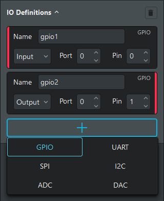
An IO definition specifies how the external program communicates with its environment. In case of a GPIO definition, the external program communicates with its environment through a digital input or output.
- Add 3 more GPIO definitions, so that there are 6 GPIO definitions in total.
- In the first IO definition 'gpio1', change Input to Output to configure the pin as a digital output.
- Change the names of the 6 GPIO definitions to:
- MainRed
- MainOrange
- MainGreen
- SideRed
- SideOrange
- SideGreen
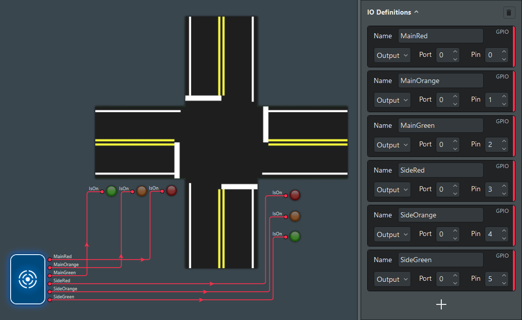
At this point, the Application component is configured to have 6 digital outputs. All outputs have a port id 0 and the pin id ranges from 0 to 5.
- In the Diagram, connect the output ports of the Application component to the corresponding Light components. The resulting model and Application component configuration looks as follows.
Programming the controller
The controller for the traffic lights is an application written in C. The tutorial uses the free Visual Studio 2019 Community IDE, but the steps should be easy to replicate in any other IDE or directly from the command line.
Adding a main file
- Install Visual Studio, and make sure that the Desktop development with C++ workload is selected during the installation.
- In Visual Studio 2015 or older, make sure that the Visual C++ feature is selected during the installation.
- Open Visual Studio and click Create a new project.
- Filter the project types by C++.
- Select Empty Project and click Next.
- Name the project 'TrafficLightController', uncheck Place solution and project in the same directory, and click Create. An empty project is created.
- In the Solution Explorer, right click Source Files and in the context menu click on Add → New Item.
- Name the file 'main.c' and click Add.
Adding the Studio Technix C library.
To access the simulation interface API functions, the C application must reference the Studio Technix library. The library comes in the form of two files: technix.h and technix.c. These files can be found in the installation directory of Studio Technix or can be downloaded here.
- Copy the
technix.handtechnix.cfiles to the project directory that contains themain.cfile. - In Visual Studio, right click Header Files and in the context menu click on Add → Existing Item.
- In the File dialog, select the
technix.hfile and click Add. This includes the library header file in the project. - Right click Source Files and in the context menu click on Add → Existing Item.
- In the File dialog, select the
technix.cfile and click Add. This adds the source of the library to the project.
Adding code
In the main.c file, add the following line to include the technix.h header file.
#include "technix.h"
Next, define the port and pin for each light as a constant.
#include <stdint.h>

const uint32_t MAIN_PORT = 0;
const uint32_t MAIN_RED_PIN = 0;
const uint32_t MAIN_ORANGE_PIN = 1;
const uint32_t MAIN_GREEN_PIN = 2;

const uint32_t SIDE_PORT = 0;
const uint32_t SIDE_RED_PIN = 3;
const uint32_t SIDE_ORANGE_PIN = 4;
const uint32_t SIDE_GREEN_PIN = 5;
Add the main function of the program.
int main(void)
{

}
At initialization, all traffic lights will be set to red. The code below uses the tx_gpio_pin_set() function to set the digital output corresponding to the red light of the main and side street to true (light is on). A delay of 1 second is introduced with the tx_delay_millis() function.
int main(void)
{
    // Turn on red light in both directions.
    tx_gpio_pin_set(MAIN_PORT, MAIN_RED_PIN, true);
    tx_gpio_pin_set(SIDE_PORT, SIDE_RED_PIN, true);
    tx_delay_millis(1000);
}
Next, an infinite loop is entered. For now, we'll just replicate the timing sequence of the lights from the previous tutorial, but this time with code.
- The main road light turns Green for 5 seconds.
- The main road light turns Orange for 2 second.
- All lights are Red for 1 second.
- The side road light turns Green for 5 seconds.
- The side road light turns Orange for 2 second.
- All lights are Red for 1 second.
- Back to step 1.
int main(void)
{
    // Turn on red light in both directions.
    tx_gpio_pin_set(MAIN_PORT, MAIN_RED_PIN, true);
    tx_gpio_pin_set(SIDE_PORT, SIDE_RED_PIN, true);
    tx_delay_millis(1000);

    while (1)
    {
        // Turn on green light on the main road (red on side road).
        tx_gpio_pin_set(MAIN_PORT, MAIN_RED_PIN, false);
        tx_gpio_pin_set(MAIN_PORT, MAIN_GREEN_PIN, true);
        tx_delay_millis(5000);

        // Turn on orange light on the main road (red on side road).
        tx_gpio_pin_set(MAIN_PORT, MAIN_GREEN_PIN, false);
        tx_gpio_pin_set(MAIN_PORT, MAIN_ORANGE_PIN, true);
        tx_delay_millis(2000);

        // Turn on red light on the main road (red on side road).
        tx_gpio_pin_set(MAIN_PORT, MAIN_ORANGE_PIN, false);
        tx_gpio_pin_set(MAIN_PORT, MAIN_RED_PIN, true);
        tx_delay_millis(1000);

        // Turn on green light on the side road (red on main road).
        tx_gpio_pin_set(SIDE_PORT, SIDE_RED_PIN, false);
        tx_gpio_pin_set(SIDE_PORT, SIDE_GREEN_PIN, true);
        tx_delay_millis(5000);

        // Turn on orange light on the side road (red on main road).
        tx_gpio_pin_set(SIDE_PORT, SIDE_GREEN_PIN, false);
        tx_gpio_pin_set(SIDE_PORT, SIDE_ORANGE_PIN, true);
        tx_delay_millis(2000);

        // Turn on red light on the side road (red on main road).
        tx_gpio_pin_set(SIDE_PORT, SIDE_ORANGE_PIN, false);
        tx_gpio_pin_set(SIDE_PORT, SIDE_RED_PIN, true);
        tx_delay_millis(1000);
    }
}
At this point, the program has the typical structure of an embedded software program that would be run on a real embedded device. However, these
tx_functionsliketx_gpio_pin_set()are a bit odd though. In a real application, you would make use of your HAL functions of choice (e.g.HAL_GPIO_WritePin()for the STM32 ordigitalWrite()for Arduino) instead. There would also be more code dedicated to the initialization of the hardware. For this reason, in the next tutorial, we'll refine the controller code further and create an abstraction that wraps thetx_functions()in a so called Virtual Hardware Abstraction Layer (Virtual HAL).
Compiling as a DLL
Studio Technix controls the execution of the target application such that the simulation results are deterministic. To this end, the application must be compiled as a DLL instead of an executable. The technix.h file already defines the necessary entry points for the DLL, so compiling as a DLL can be achieved as follows.
- In Visual Studio, in the Solution Explorer, right click on the project TrafficLightController and click Properties. The TrafficLightController Property Pages window appears.
- In the tab Configuration Properties → General, set Configuration Type to Dynamic Library (.dll).
- Click OK to apply the new settings.
- Right click on the project TrafficLightController again and click Build to compile the DLL. The resulting DLL can be found in Debug folder that has been generated.
Importing the application DLL in Studio Technix
- In Studio Technix, click on the Application component to select it, and in the Properties panel, locate the Application DLL parameter.
- Click on the '...' button, and open the 'TrafficLightController.dll' file which is located in the 'Debug' folder of the Visual Studio Project.
- Leave the other parameters of the Application component at their default values.
Running a software-in-the-loop simulation
The simulation settings can be left at their default values.
To start the simulation:
- In the Menu bar, click on the Play button (
 ).
).
The Simulation starts to run, and you should see the following animation in real-time. The light sequence is the same as in the previous tutorial, but this time the lights are controlled by an external program. This kind of simulation is called Software-In-the-Loop simulation, or SIL simulation for short.
Extending the model with a sensor for detecting vehicles
A common system to detect the presence of vehicles at a red light is an induction loop that is buried in the road. When a vehicle drives over the induction loop, an electric current is generated which can be detected by a sensor.
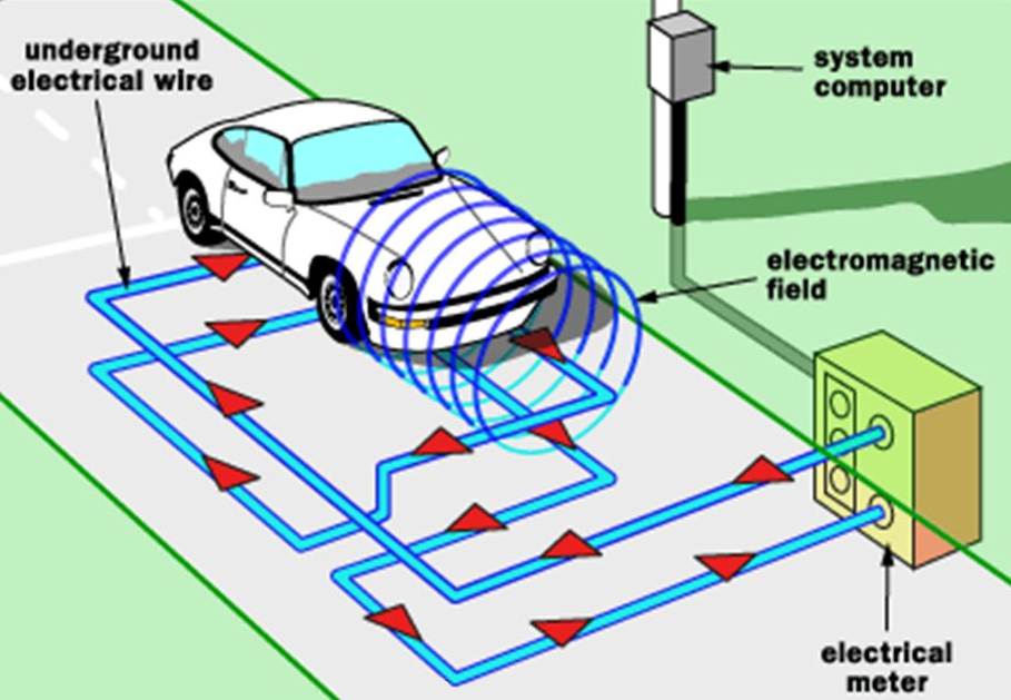
Modeling the sensor
From a software perspective the induction loop circuit is presented as a digital input signal: a vehicle is present or not.
In Studio Technix, this can be modeled by adding an extra GPIO Definition of type input to the Application component:
- In Studio Technix, click on the Application component to select it.
- In the Properties panel, click the '+' button and select GPIO to add a new GPIO definition. A GPIO definition is appended to the bottom of the IO Definitions list.
- Set the name of the new GPIO definition to 'HasVehicles'.
- Change the type of the 'HasVehicles' GPIO from Output to Input.
- Set the Port to
1, and the Pin to0.
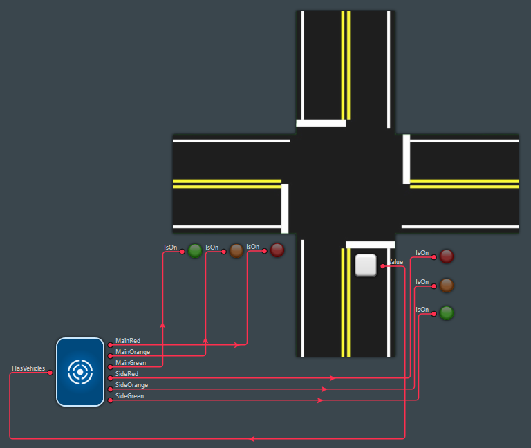
To generate a signal for this sensor input, there are multiple suitable components in Studio Technix. In this case, we'll use a PushButton component such that you can interactively generate a signal in real-time. In this case, a pressed PushButton means that a vehicle is present within the induction loop and an unpressed PushButton means that no vehicles are present.
- In the Component Library panel, in the Target Library, locate the PushButton component (
 ).
). - Drag the PushButton component onto the Diagram and place it on top of the side road, just below the stop line. The pushbutton represents the induction loop in the road at that location.
- Connect the Value port of the PushButton component to the HasVehicles port of the Application component.
Alternatively, the Pulse component could be used to generate a repeating sequence of arriving cars. Or the File Reader component could be used to generate any desired sequence of arriving cars based on a data table in an external file.
Updating the controller
In the main.c file add two lines at the top of the file to define a constant for the sensors port and pin number.
const uint32_t VEHICLE_SENSOR_PORT = 1;
const uint32_t VEHICLE_SENSOR_PIN = 0;
In the while-loop of the main() function add the following lines in between the 'Turn on green light on the main road' and 'Turn on orange light on the main road' code blocks.
// Check for any vehicles on the side road sensor before continuing.
while (!tx_gpio_pin_get(VEHICLE_SENSOR_PORT, VEHICLE_SENSOR_PIN))
{
    tx_cycle();
}
The complete main.c file now looks as follows.
#include "technix.h"
#include <stdint.h>

const uint32_t MAIN_PORT = 0;
const uint32_t MAIN_RED_PIN = 0;
const uint32_t MAIN_ORANGE_PIN = 1;
const uint32_t MAIN_GREEN_PIN = 2;

const uint32_t SIDE_PORT = 0;
const uint32_t SIDE_RED_PIN = 3;
const uint32_t SIDE_ORANGE_PIN = 4;
const uint32_t SIDE_GREEN_PIN = 5;

const uint32_t VEHICLE_SENSOR_PORT = 1;
const uint32_t VEHICLE_SENSOR_PIN = 0;

int main(void)
{
    // Turn on red light in both directions.
    tx_gpio_pin_set(MAIN_PORT, MAIN_RED_PIN, true);
    tx_gpio_pin_set(SIDE_PORT, SIDE_RED_PIN, true);
    tx_delay_millis(1000);

    while (1)
    {
        // Turn on green light on the main road (red on side road).
        tx_gpio_pin_set(MAIN_PORT, MAIN_RED_PIN, false);
        tx_gpio_pin_set(MAIN_PORT, MAIN_GREEN_PIN, true);
        tx_delay_millis(5000);

        // Check for any vehicles on the side road sensor before continuing.
        while (!tx_gpio_pin_get(VEHICLE_SENSOR_PORT, VEHICLE_SENSOR_PIN))
        {
            tx_cycle();
        }

        // Turn on orange light on the main road (red on side road).
        tx_gpio_pin_set(MAIN_PORT, MAIN_GREEN_PIN, false);
        tx_gpio_pin_set(MAIN_PORT, MAIN_ORANGE_PIN, true);
        tx_delay_millis(2000);

        // Turn on red light on the main road (red on side road).
        tx_gpio_pin_set(MAIN_PORT, MAIN_ORANGE_PIN, false);
        tx_gpio_pin_set(MAIN_PORT, MAIN_RED_PIN, true);
        tx_delay_millis(1000);

        // Turn on green light on the side road (red on main road).
        tx_gpio_pin_set(SIDE_PORT, SIDE_RED_PIN, false);
        tx_gpio_pin_set(SIDE_PORT, SIDE_GREEN_PIN, true);
        tx_delay_millis(5000);

        // Turn on orange light on the side road (red on main road).
        tx_gpio_pin_set(SIDE_PORT, SIDE_GREEN_PIN, false);
        tx_gpio_pin_set(SIDE_PORT, SIDE_ORANGE_PIN, true);
        tx_delay_millis(2000);

        // Turn on red light on the side road (red on main road).
        tx_gpio_pin_set(SIDE_PORT, SIDE_ORANGE_PIN, false);
        tx_gpio_pin_set(SIDE_PORT, SIDE_RED_PIN, true);
        tx_delay_millis(1000);
    }
}
The code works as follows. After entering the main while loop, the main traffic light is turned green. Then, after a delay of 5 seconds, in a busy while-loop it is checked whether a vehicle is present in the side road. If that is the case, the light sequence continues, such that the traffic light in the side road turns green and eventually the sequences arrives back at a green traffic light in the main road.
The second busy while-loop does not perform any work besides checking whether the digital input of the sensor is true. Because no timing functions like tx_delay_millis() are present, the special tx_cycle() function must be added to the loop. This function indicates to the simulator that it should simulate the reaction of the environment and update the application's input ports. It is also required to obtain a deterministic simulation. The mechanism is explained in detail in the article Timing Considerations.
Recompiling and running the simulation
- In Visual Studio, right click on the project TrafficLightController and click Build to compile the new code.
- In Studio Technix, click the Play button to start the Simulation. The simulator will reload the application DLL and thus take into account the changes that were made to the code.
At the simulation start, all lights are red. Then the main traffic light turns green. It remains green at least 5 seconds. After 5 seconds, if a vehicle is detected in the side road (= the PushButton is pressed), the light sequence changes and the light in the side road turns green. If no vehicle is detected, the traffic light on the main road remains green.
Once the traffic light in the side road turns red again, the main traffic light turns green for at least 5 seconds before the controller will try to detect another vehicle in the side road.
This completes the tutorial.
In the next tutorial the tx_functions will be wrapped in a so called Virtual Hardware Abstraction Layer (Virtual HAL). This way the application layer code for the real device and the virtual device will be identical and the virtual HAL can be swapped out for a real HAL in case the application is deployed to an embedded device.
Sources
Download the initial project files.
Download the final project files.