Tutorial: Traffic Light Controller with Virtual HAL
In this tutorial you will rewrite the code for the traffic light controller of the previous Traffic Light Controller tutorial to use a Virtual Hardware Abstraction Layer (Virtual HAL). This way, the application layer code of the simulated system will be identical to that of the real embedded system. As a consequence, the application code developed using simulation can be deployed unchanged on the embedded device by swapping out the virtual HAL for the real device HAL. This tutorial has been created using the Blue Pill board based on the STM32F103 microcontroller and the STM32CubeMX HAL, but the tutorial also works for any other STM32 microcontroller.
Objective
The starting point of this tutorial is the Traffic Light Controller project developed in the Traffic Light Controller tutorial.
The main() function currently makes use of tx_functions as shown below.
int main(void)
{
    // Turn on red light in both directions.
    tx_gpio_pin_set(MAIN_PORT, MAIN_RED_PIN, true);
    tx_gpio_pin_set(SIDE_PORT, SIDE_RED_PIN, true);
    tx_delay_millis(1000);

    while (1)
    {
        // Turn on green light on the main road (red on side road).
        tx_gpio_pin_set(MAIN_PORT, MAIN_RED_PIN, false);
        tx_gpio_pin_set(MAIN_PORT, MAIN_GREEN_PIN, true);
        tx_delay_millis(5000);

        // Check for any vehicles on the side road sensor before continuing.
        while (!tx_gpio_pin_get(VEHICLE_SENSOR_PORT, VEHICLE_SENSOR_PIN))
        {
            tx_cycle();
        }

        // Turn on orange light on the main road (red on side road).
        tx_gpio_pin_set(MAIN_PORT, MAIN_GREEN_PIN, false);
        tx_gpio_pin_set(MAIN_PORT, MAIN_ORANGE_PIN, true);
        tx_delay_millis(2000);

        // Turn on red light on the main road (red on side road).
        tx_gpio_pin_set(MAIN_PORT, MAIN_ORANGE_PIN, false);
        tx_gpio_pin_set(MAIN_PORT, MAIN_RED_PIN, true);
        tx_delay_millis(1000);

        // Turn on green light on the side road (red on main road).
        tx_gpio_pin_set(SIDE_PORT, SIDE_RED_PIN, false);
        tx_gpio_pin_set(SIDE_PORT, SIDE_GREEN_PIN, true);
        tx_delay_millis(5000);

        // Turn on orange light on the side road (red on main road).
        tx_gpio_pin_set(SIDE_PORT, SIDE_GREEN_PIN, false);
        tx_gpio_pin_set(SIDE_PORT, SIDE_ORANGE_PIN, true);
        tx_delay_millis(2000);

        // Turn on red light on the side road (red on main road).
        tx_gpio_pin_set(SIDE_PORT, SIDE_ORANGE_PIN, false);
        tx_gpio_pin_set(SIDE_PORT, SIDE_RED_PIN, true);
        tx_delay_millis(1000);
    }
}
Two projects will be created during this tutorial. One project will target the STM32F103 microcontroller, the other project will target a model of the system in Studio Technix simulation.
The objective of this tutorial is to write the code in such way that the tx_functions are abstracted away in a Virtual Hardware Abstraction Layer (Virtual HAL) that is compatible with the STM32CubeMX HAL, so that the code that targets the real STM32 device and the simulation in Studio Technix is identical and looks as follows.
int main(void)
{
    HAL_Init();
    SystemClock_Config();
    MX_GPIO_Init();

    // Turn on red light in both directions.
    HAL_GPIO_WritePin(MAIN_PORT, MAIN_RED_PIN, GPIO_PIN_SET);
    HAL_GPIO_WritePin(SIDE_PORT, SIDE_RED_PIN, GPIO_PIN_SET);
    HAL_Delay(1000);

    while (1)
    {
        // Turn on green light on the main road (red on side road).
        HAL_GPIO_WritePin(MAIN_PORT, MAIN_RED_PIN, GPIO_PIN_RESET);
        HAL_GPIO_WritePin(MAIN_PORT, MAIN_GREEN_PIN, GPIO_PIN_SET);
        HAL_Delay(5000);

        // Check for any vehicles on the side road sensor before continuing.
        while (HAL_GPIO_ReadPin(VEHICLE_SENSOR_PORT, VEHICLE_SENSOR_PIN)
                  != GPIO_PIN_SET)
        {
#if SIM
            tx_cycle();
#endif
        }

        // Turn on orange light on the main road (red on side road).
        HAL_GPIO_WritePin(MAIN_PORT, MAIN_GREEN_PIN, GPIO_PIN_RESET);
        HAL_GPIO_WritePin(MAIN_PORT, MAIN_ORANGE_PIN, GPIO_PIN_SET);
        HAL_Delay(2000);

        // Turn on red light on the main road (red on side road).
        HAL_GPIO_WritePin(MAIN_PORT, MAIN_ORANGE_PIN, GPIO_PIN_RESET);
        HAL_GPIO_WritePin(MAIN_PORT, MAIN_RED_PIN, GPIO_PIN_SET);
        HAL_Delay(1000);

        // Turn on green light on the side road (red on main road).
        HAL_GPIO_WritePin(SIDE_PORT, SIDE_RED_PIN, GPIO_PIN_RESET);
        HAL_GPIO_WritePin(SIDE_PORT, SIDE_GREEN_PIN, GPIO_PIN_SET);
        HAL_Delay(5000);

        // Turn on orange light on the side road (red on main road).
        HAL_GPIO_WritePin(SIDE_PORT, SIDE_GREEN_PIN, GPIO_PIN_RESET);
        HAL_GPIO_WritePin(SIDE_PORT, SIDE_ORANGE_PIN, GPIO_PIN_SET);
        HAL_Delay(2000);

        // Turn on red light on the side road (red on main road).
        HAL_GPIO_WritePin(SIDE_PORT, SIDE_ORANGE_PIN, GPIO_PIN_RESET);
        HAL_GPIO_WritePin(SIDE_PORT, SIDE_RED_PIN, GPIO_PIN_SET);
        HAL_Delay(1000);
    }
}
Generating boilerplate with STM32CubeMX
First, we'll create a project that targets the real STM32 microcontroller. We'll make use of the STM23CubeMX tool to generate the boilerplate code and the necessary STM32CubeMX HAL files. Afterwards we'll create a virtual HAL with the same interface functions.
- Install and open the STM32CubeMX tool.
- In the New Project of the welcome screen, click the Access to MCU Selector button. The New Project from a MCU/MPU window appears.
- In the Part Number textbox, fill in 'STM32F103C8', which is the microcontroller for the Blue Pill board. The MCUs/MPUs List reduces to a single item.
- Double click the STM32F103C8 item in the MCUs/MPUs List. The main STM32CubeMX Pinout & Configuration window appears.
- In the left pane select the System Core->SYS category.
- Set Debug to Serial Wire.
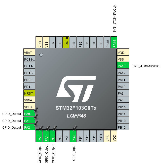
- In the Pinout View diagram, left click the PA0 and in the popup menu select GPIO_Output.
- Repeat this last step for pins PA1, PA2, PA3, PA4, PA5.
- Left click the PB0 and in the popup menu select GPIO_Input.
The pinout diagram now looks as follows.
Next the STM32CubeMX project settings are configured.
- In the Project Manager tab, set Project Name to 'TrafficLightDevice'.
- Set Project Location to the directory corresponding to the Traffic Light Controller solution folder.
- Set Toolchain / IDE to Other Toolchains (GPDSC) when using Visual GDB for Visual Studio, or to any other toolchain of choice.
- Click the Generate Code button at the top right of the window to generate the boilerplate code.
The code can now be imported in your favorite IDE. The following instructions are for importing the generated code in Visual Studio using the excellent Visual GDB add in.
- In Visual Studio, in the Solution Explorer, right click on the TrafficLightController solution and in the popup menu click on Add → New Project. The Add a new project window appears.
- Search for 'Embedded' in the Search for templates text box, select Embedded Project Wizard, and click Next. The Configure your new project screen appears.
- Name the project 'TrafficLightDevice' and click Create. The Visual GDB New Embedded Project wizard appears.
- Select the option Automatically import a project in a different format, then select Import an existing STM32CubeMX Project (GPDSC)
- In the Project File edit box, click on the folder icon and browse to the folder where the STM32CubeMX project was generated. Open the TrafficLightDevice.gpdsc file.
- Check Move the Visual Studio project to the imported project directory and Rename the Visual Studio project to match the imported project name.
- Click Next. In the Device Selection tab, the STM32F103C8 device is automatically selected.
- Click Next again. A window with Visual GDB is testing the selected toolchain popups for a brief time. Then the Debug Method tab appears.
- Set JTAG/SWD programmer to ST-Link v2.1.
- Click Finish to finish the importing of the STM32CubeMX project in Visual Studio.
Rearranging code to improve separation of concerns
The code that is generated by STM32CubeMX follows a particular structure and contains a lot of comments to make automatic code generation and updating easier. We'll clean up the code and restructure the code such that the main controller loop is separated from the device peripherals initialization.
Create a new header file
init.hand add the declarations of the HAL initialization functions.#ifndef __INIT_H #define __INIT_H #include "stm32f1xx_hal.h" void SystemClock_Config(void); void MX_GPIO_Init(void); void Error_Handler(void); #endifCreate a new code file
init.cand move theSystemClock_Config,MX_GPIO_InitandError_Handlerfunctions from themain.ctoinit.c.Remove
staticfrom the signature ofMX_GPIO_Init. Theinit.cnow looks as:#include "init.h" void SystemClock_Config(void) { RCC_OscInitTypeDef RCC_OscInitStruct = { 0 }; RCC_ClkInitTypeDef RCC_ClkInitStruct = { 0 }; /** Initializes the RCC Oscillators according to the specified parameters * in the RCC_OscInitTypeDef structure. */ RCC_OscInitStruct.OscillatorType = RCC_OSCILLATORTYPE_HSI; RCC_OscInitStruct.HSIState = RCC_HSI_ON; RCC_OscInitStruct.HSICalibrationValue = RCC_HSICALIBRATION_DEFAULT; RCC_OscInitStruct.PLL.PLLState = RCC_PLL_NONE; if (HAL_RCC_OscConfig(&RCC_OscInitStruct) != HAL_OK) { Error_Handler(); } /** Initializes the CPU, AHB and APB buses clocks */ RCC_ClkInitStruct.ClockType = RCC_CLOCKTYPE_HCLK | RCC_CLOCKTYPE_SYSCLK | RCC_CLOCKTYPE_PCLK1 | RCC_CLOCKTYPE_PCLK2; RCC_ClkInitStruct.SYSCLKSource = RCC_SYSCLKSOURCE_HSI; RCC_ClkInitStruct.AHBCLKDivider = RCC_SYSCLK_DIV1; RCC_ClkInitStruct.APB1CLKDivider = RCC_HCLK_DIV1; RCC_ClkInitStruct.APB2CLKDivider = RCC_HCLK_DIV1; if (HAL_RCC_ClockConfig(&RCC_ClkInitStruct, FLASH_LATENCY_0) != HAL_OK) { Error_Handler(); } } void MX_GPIO_Init(void) { GPIO_InitTypeDef GPIO_InitStruct = { 0 }; /* GPIO Ports Clock Enable */ __HAL_RCC_GPIOC_CLK_ENABLE(); __HAL_RCC_GPIOD_CLK_ENABLE(); __HAL_RCC_GPIOA_CLK_ENABLE(); __HAL_RCC_GPIOB_CLK_ENABLE(); /*Configure GPIO pin Output Level */ HAL_GPIO_WritePin(GPIOA, GPIO_PIN_0|GPIO_PIN_1|GPIO_PIN_2|GPIO_PIN_3 |GPIO_PIN_4|GPIO_PIN_5, GPIO_PIN_RESET); /*Configure GPIO pins : PA0 PA1 PA2 PA3 PA4 PA5 */ GPIO_InitStruct.Pin = GPIO_PIN_0 | GPIO_PIN_1 | GPIO_PIN_2 | GPIO_PIN_3 | GPIO_PIN_4 | GPIO_PIN_5; GPIO_InitStruct.Mode = GPIO_MODE_OUTPUT_PP; GPIO_InitStruct.Pull = GPIO_NOPULL; GPIO_InitStruct.Speed = GPIO_SPEED_FREQ_LOW; HAL_GPIO_Init(GPIOA, &GPIO_InitStruct); /*Configure GPIO pin : PB0 */ GPIO_InitStruct.Pin = GPIO_PIN_0; GPIO_InitStruct.Mode = GPIO_MODE_INPUT; GPIO_InitStruct.Pull = GPIO_NOPULL; HAL_GPIO_Init(GPIOB, &GPIO_InitStruct); void Error_Handler(void) { } }In
main.h, remove all STM32CubeMX generated comments, and theError_Handlerdeclaration:#ifndef __MAIN_H #define __MAIN_H #include "stm32f1xx_hal.h" #endifIn
main.c, remove all STM32CubeMX generated comments, and includeinit.h#include "main.h" #include "init.h" int main(void) { HAL_Init(); SystemClock_Config(); MX_GPIO_Init(); while (1) { } }
Implementing the algorithm targeting the physical device
To complete the code for the real device, the HAL API-functions for getting and setting digital ports are used for implementing the traffic light controller algorithm.
First, in
main.h, add constant definitions for the port and pin numbers:#ifndef __MAIN_H #define __MAIN_H #include "stm32f1xx_hal.h" #define MAIN_PORT GPIOA #define MAIN_RED_PIN GPIO_PIN_0 #define MAIN_ORANGE_PIN GPIO_PIN_1 #define MAIN_GREEN_PIN GPIO_PIN_2 #define SIDE_PORT GPIOA #define SIDE_RED_PIN GPIO_PIN_3 #define SIDE_ORANGE_PIN GPIO_PIN_4 #define SIDE_GREEN_PIN GPIO_PIN_5 #define VEHICLE_SENSOR_PORT GPIOB #define VEHICLE_SENSOR_PIN GPIO_PIN_0 #endifThen, in
main.cadd the following calls.#include "main.h" #include "init.h" int main(void) { HAL_Init(); SystemClock_Config(); MX_GPIO_Init(); // Turn on red light in both directions. HAL_GPIO_WritePin(MAIN_PORT, MAIN_RED_PIN, GPIO_PIN_SET); HAL_GPIO_WritePin(SIDE_PORT, SIDE_RED_PIN, GPIO_PIN_SET); HAL_Delay(1000); while (1) { // Turn on green light on the main road (red on side road). HAL_GPIO_WritePin(MAIN_PORT, MAIN_RED_PIN, GPIO_PIN_RESET); HAL_GPIO_WritePin(MAIN_PORT, MAIN_GREEN_PIN, GPIO_PIN_SET); HAL_Delay(5000); // Check for any vehicles on the side road sensor before continuing. while(HAL_GPIO_ReadPin(VEHICLE_SENSOR_PORT, VEHICLE_SENSOR_PIN) != GPIO_PIN_SET) { } // Turn on orange light on the main road (red on side road). HAL_GPIO_WritePin(MAIN_PORT, MAIN_GREEN_PIN, GPIO_PIN_RESET); HAL_GPIO_WritePin(MAIN_PORT, MAIN_ORANGE_PIN, GPIO_PIN_SET); HAL_Delay(2000); // Turn on red light on the main road (red on side road). HAL_GPIO_WritePin(MAIN_PORT, MAIN_ORANGE_PIN, GPIO_PIN_RESET); HAL_GPIO_WritePin(MAIN_PORT, MAIN_RED_PIN, GPIO_PIN_SET); HAL_Delay(1000); // Turn on green light on the side road (red on main road). HAL_GPIO_WritePin(SIDE_PORT, SIDE_RED_PIN, GPIO_PIN_RESET); HAL_GPIO_WritePin(SIDE_PORT, SIDE_GREEN_PIN, GPIO_PIN_SET); HAL_Delay(5000); // Turn on orange light on the side road (red on main road). HAL_GPIO_WritePin(SIDE_PORT, SIDE_GREEN_PIN, GPIO_PIN_RESET); HAL_GPIO_WritePin(SIDE_PORT, SIDE_ORANGE_PIN, GPIO_PIN_SET); HAL_Delay(2000); // Turn on red light on the side road (red on main road). HAL_GPIO_WritePin(SIDE_PORT, SIDE_ORANGE_PIN, GPIO_PIN_RESET); HAL_GPIO_WritePin(SIDE_PORT, SIDE_RED_PIN, GPIO_PIN_SET); HAL_Delay(1000); } }
This completes the code for the physical device, and it can be compiled and deployed to the Blue Pill board.
Implementing the algorithm targeting the simulated traffic light system
This section shows how to create a virtual HAL for a device based on a real HAL for that device. The real HAL API-functions will by replaced, step-by-step, by functions with the same signature, that wrap the Studio Technix API. The register structure pointers will be replaced by in memory structure pointers. In the end, the virtual HAL will contain the same data structures and functions as the the real HAL.
Duplicating files that do not need to be changed
A new project is created for the traffic light controller with virtual HAL.
- In Visual Studio, in the Solution Explorer, right click on the TrafficLightController solution and in the popup menu click on Add → New Project. The Add a new project window appears.
- Filter the project types by C++. Select Empty Project and click Next.
- Name the project 'TrafficLightMockup' and click Create.
A number of existing files can be copied unmodified to the new project.
- Copy
technix.handtechnix.cfrom the TrafficLightController project to respectively the Header Files and Source Files directory of the new project. - Copy
main.handmain.cfrom the TrafficLightController project to respectively the Header Files and Source Files directory of the new project. - Copy
init.hfrom the TrafficLightController project to the Header Files directory of the new project.
Mockup for the HAL initialization functions
Since the virtual HAL targets the simulated system, and the simulation model currently does not simulate GPIO faults, the HAL initialization mockup functions can be left empty.
Add a new source file
init.cand add the following empty HAL initialization functions:#include "init.h" void SystemClock_Config(void) { // Mock: do nothing. } void MX_GPIO_Init(void) { // Mock: do nothing. } void Error_Handler(void) { // Mock: do nothing. }
Mockup for the HAL header file stm32f1xx_hal.h
The stm32f1xx_hal.c and stm32f1xx_hal.h are the front-end files to the STM32CubeMX HAL library. The stm32f1xx_hal.h includes any module specific (e.g. GPIO) type and function declarations that are used by an application. We'll only port the parts of the HAL that are effectively used by the traffic light controller.
In the TrafficLightMockup project, add a new header file stm32f1xx_hal.h and add the following boiler plate code:
#ifndef __STM32F4xx_HAL_H
#define __STM32F4xx_HAL_H

#include <stdint.h>

#endif
Mockup of structs and enums
First, we'll create mockup definitions of HAL structs and enums that are used. The GPIO_PinState and HAL_StatusTypeDef enums are direct copies from the original HAL.
typedef enum
{
    GPIO_PIN_RESET = 0,
    GPIO_PIN_SET
} GPIO_PinState;

typedef enum
{
    HAL_OK = 0x00U,
    HAL_ERROR = 0x01U,
    HAL_BUSY = 0x02U,
    HAL_TIMEOUT = 0x03U
} HAL_StatusTypeDef;
The GPIO_TypeDef struct is defined differently. Instead of specifying the register layout like the original HAL, we'll add a single PortId member, which will be sufficient to identify the Studio Technix port id, later on in the implementation of the GPIO HAL functions.
typedef struct
{
    uint32_t PortId;
} GPIO_TypeDef;
Function declarations
Next, the function prototypes of the HAL functions that are used, are directly copied from the original HAL.
HAL_StatusTypeDef HAL_Init(void);
void HAL_GPIO_WritePin(GPIO_TypeDef* GPIOx, uint16_t GPIO_Pin, GPIO_PinState PinState);
GPIO_PinState HAL_GPIO_ReadPin(GPIO_TypeDef* GPIOx, uint16_t GPIO_Pin);
void HAL_Delay(uint32_t Delay);
Mapping the register structs to mockups in memory
The original HAL defines GPIOA and GPIOB as memory mapped register pointers. The simulation will not involve any real hardware, so instead, we initialize a mockup instance in memory:
static const GPIO_TypeDef GPIOA_MOCK = { 0 };
static const GPIO_TypeDef GPIOB_MOCK = { 1 };
and map the GPIO pointer to the mockup in memory:
#define GPIOA  (&GPIOA_MOCK)
#define GPIOB  (&GPIOB_MOCK)
Note that the GPIOA_MOCK and GPIOB_MOCK mock define a value for the PortId to distinguish the two.
Mocking constants
Finally, constants that are defined in the original HAL must be replaced by an equivalent mockup value. In this case the original HAL constants can be copied directly from the orignal HAL:
#define GPIO_PIN_0      (0)
#define GPIO_PIN_1      (1)
#define GPIO_PIN_2      (2)
#define GPIO_PIN_3      (3)
#define GPIO_PIN_4      (4)
#define GPIO_PIN_5      (5)
#define GPIO_PIN_6      (6)
#define GPIO_PIN_7      (7)
#define GPIO_PIN_8      (8)
#define GPIO_PIN_9      (9)
#define GPIO_PIN_10     (10)
#define GPIO_PIN_11     (11)
#define GPIO_PIN_12     (12)
#define GPIO_PIN_13     (13)
#define GPIO_PIN_14     (14)
#define GPIO_PIN_15     (15)

#define HAL_MAX_DELAY       0xFFFFFFFFU
Mockup for the HAL implementation file stm32f1xx_hal.c
The actual implementation of the virtual HAL functions will be considerably different from the original HAL. Instead of manipulating registers, the virtual HAL functions will transform the function inputs and outputs to match the Studio Technix API functions.
In the TrafficLightMockup project, add a new source file stm32f1xx_hal.c and add the following includes:
#include <stdint.h>
#include <stdbool.h>
#include "stm32f1xx_hal.h"
#include "technix.h"
The mockup of the HAL_Init() always returns successfully, because the simulation model does not simulate failures.
HAL_StatusTypeDef HAL_Init(void)
{
    return HAL_OK;
}
The HAL_Delay() can be mocked by calling tx_delay_millis with the same argument.
void HAL_Delay(uint32_t Delay)
{
    tx_delay_millis(Delay);
}
The mockup of HAL_GPIO_WritePin() wraps the tx_gpio_pin_set function. Here we make use of the earlier defined PortId member of the GPIO_TypeDef mockup. This PortId is now used as the port parameter for the tx_gpio_pin_set function. The GPIO_Pin does not need to be transformed. The PinState parameter is transformed to a bool with a simple expression.
void HAL_GPIO_WritePin(GPIO_TypeDef* GPIOx, uint16_t GPIO_Pin, GPIO_PinState PinState)
{
    tx_gpio_pin_set(GPIOx->PortId, GPIO_Pin, PinState == GPIO_PIN_SET ? true : false);
}
In a similar fashion the mockup of HAL_GPIO_ReadPin transforms its input and output parameters so it matches the tx_gpio_pin_get function.
GPIO_PinState HAL_GPIO_ReadPin(GPIO_TypeDef* GPIOx, uint16_t GPIO_Pin)
{
    return tx_gpio_pin_get(GPIOx->PortId, GPIO_Pin) ? GPIO_PIN_SET : GPIO_PIN_RESET;
}
Compiling the virtual HAL
The virtual HAL is now finished.
Compile the TrafficLightMockup project as a DLL, so it can be used in Studio Technix.
- Right click on the project TrafficLightMockup and click Properties. The TrafficLightMockup Property Pages window appears.
- In the tab Configuration Properties → General, set Configuration Type to Dynamic Library (.dll).
- Click OK to apply the new settings.
- Right click on the project TrafficLightMockup again and click Build to compile the DLL. The resulting DLL can be found in Debug folder that has been generated.
Simulating the application using the virtual HAL
A first try of the virtual HAL
It is now possible to import the TrafficLightMockup DLL based on the virtual HAL in Studio Technix.
- In Studio Technix, click on the Application component to select it, and in the Properties panel, locate the Application DLL parameter.
- Click on the '...' button, and open the 'TrafficLightMockup.dll' file which is located in the 'Debug' folder of the Visual Studio Project.
- In the Menu bar, click on the Play button (
 ) to start the simulation.
The simulation starts to run. However, after running 6 seconds, the simulation stops and issues the error
The number of yields in this cycle has exceeded the maximum of '1000 [yields/cycle]'. Is there a call to `tx_cycle` in your main loop?
The reason is that the busy loop that checks for any vehicles on the side road sensor is empty, and because of that the simulator cannot advance the simulation time in any meaningful way.
Solving the simulation time issue
The solution is to add a call to tx_cycle(). This function gives Studio Technix a means to progress time throughout a busy loop in a deterministic way (such that the outcome of every simulation is the same).
It is not desired that this tx_cycle() function is present in the code that targets the real hardware, so by wrapping the call in an #if SIM preprocessor directive, the call is removed when the SIM is not defined.
In main.c of both the TrafficLightDevice and TrafficLightMockup project, change the busy loop as follows
while (HAL_GPIO_ReadPin(VEHICLE_SENSOR_PORT, VEHICLE_SENSOR_PIN)
          != GPIO_PIN_SET)
{
#if SIM
    tx_cycle();
#endif
}
Add the SIM preprocessor definition to the TrafficLightMockup project only:
- Right click on the project TrafficLightMockup and click Properties. The TrafficLightMockup Property Pages window appears.
- In the tab Configuration Properties → C/C++ → Preprocessor, locate the Preprocessor Definitions property and add
SIMto the list. - Click OK to apply the new settings.
- Right click on the project TrafficLightMockup again and click Build to recompile the DLL.
In Studio Technix, run the simulation again. This time, the simulation does not issue any errors anymore.
Summary
Starting from a HAL for a real device, a virtual HAL was created. The types and functions of the HAL were replaced by mocks. Register structs were replaced by mocks in memory. HAL functions were replaced by mocks that wrap the Studio Technix API functions.
As a result, the application code targetting the real device and the virtual model in Studio Technix is identical, and targetting one or the other is a simple matter of swapping out the HAL code files.
This concludes the tutorial.
Sources
Download the initial project files.
Download the final project files.