Blinky in Studio Technix
The Blinky program is typically the first program that is written for an embedded system. It is the equivalent of Hello World in the embedded world. It only performs one task: blinking a LED on and off.
This article shows how you can create your first Blinky program in Studio Technix. First we'll make an LED blink with simulation only. But the end goal is to test embedded C code with simulation, so in the second part of the article we'll replace one of the simulation components with custom C code.
This is an overview article, for a step-by-step tutorial on how to use Studio Technix, go to the tutorials page.
Blinky with simulation only
Open a new project in Studio Technix.
Adding an LED
First we'll add a LED. From the Dashboard Library, drag the Light component (![]() ) onto the diagram.
) onto the diagram.
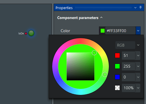
By default, the LED is red. To change the color, click on the component, and in the Properties panel, change the color to a bright green.
Adding a on/off pulse
Next, drag the Pulse component (![]() ) from the Signal Library onto the diagram, and place it to the left of the Light. By default, the Pulse component generates an analog pulsating signal. To change it to a digital signal, click on the component, and in the Properties panel, set DataType to Bool.
) from the Signal Library onto the diagram, and place it to the left of the Light. By default, the Pulse component generates an analog pulsating signal. To change it to a digital signal, click on the component, and in the Properties panel, set DataType to Bool.
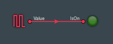
Finally, connect the output port of the Pulse component with the input port of the LED component. Now the simulation model is ready. It should look as follows.
Simulate
Start the simulation by pressing the Play button. The LED is blinking on and off with a period of 1 second. Try playing with the properties of the Pulse component. By changing the period or duration it is possible to make the LED blink faster or slower, or change the duration of the time the LED is on.
Blinky with code and simulation
In this section, we'll replace the Pulse component, by an embedded application component. We'll write the typical Blinky program in C code. Then we'll connect it to the simulator so we can blink our virtual LED from code.
Blinky C program
In your favorite code editor or IDE, create a new file main.c and add the following code:
#include "technix.h"

#define LED_PORT 0
#define LED_PIN 1

int main(void)
{
    while (1)
    {
        tx_gpio_pin_set(LED_PORT, LED_PIN, true);
        tx_delay_millis(500);
        tx_gpio_pin_set(LED_PORT, LED_PIN, false);
        tx_delay_millis(500);
    }
}
Next, add the Studio Technix API header file technix.h and source file technix.c to the project. These files can be downloaded here. Finally, compile the project as a DLL called blinky.dll (all necessary DLL exports are defined in the technix.h file).
Connecting the Blinky program with the simulator
In Studio Technix, remove the Pulse component, and drag a new Application component from the Target Library onto the diagram.
Click on it, and in the Properties panel, remove the gpio1 IO definition. Rename gpio2 to Light. Connect the Light output port of the application component to the input of the LED component.
Finally, set the Application DLL property to the path of the Blinky C program DLL you just compiled (blinky.dll).
Software-in-the-loop simulation
Press Play to start the simulation. The LED starts blinking like before. But this time, the blinking is controlled by the C program. Change the value of the delay in the C code, recompile, and observe the effect on the simulation.
Simulating an embedded program with virtual inputs and outputs, like this, is called software-in-the-loop simulation, and speeds up development considerably because experimenting is much easier and faster.
Project files
Download the project files to try out the blinky demo.